

Guest Article: From the mind of Mihail – Integrating a dumb IR controlled heat pump using ESPHome
A common problem when starting home automation is that most people have devices in their homes that do not have any Internet of Things (IoT) capability. In this article, we will focus on energy-intensive devices such as heating, cooling, and hot water systems. Older devices can often be controlled with a remote control that sends out Infra red pulses with an IR transmitter.
Heating systems often have multiple temperature sensors that control their operation. The most common thermal sensors are based on thermistors – resistors that change their value based on the temperature in a predictable way. The simplest and most obvious way of controlling a device is simply turning off the power to it with a relay or a smart outlet.
Heat Pumps and Home Assistant
Only the very latest models of heat pumps have built-in Wi-Fi capabilities and an app that you can use to control them. On some models, the app includes Home Assistant integrations, but on others, integrations are unavailable, and the API is essentially a black box.
On older heat pump models, Wi-Fi isn’t even an option, and the only way to control these devices is through the remote control.
This was the case with my Toshiba heat pump. On the Mitsubishi unit I have in the garage, it is possible to add a Wi-Fi module for a hefty additional cost. This is where Home Assistant and some add-on electronics can help.
ESP32 and ESPHome Integration
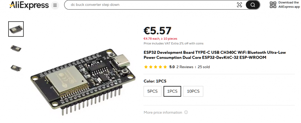
The ESP32 is a microcontroller platform similar to Arduino, but it has built-in Wi-Fi and Bluetooth capabilities, as well as very handy programming interfaces and Home Assistant integrations. ESP32 boards can be purchased from China at a very low cost of around 4 to 7 Euros.
What makes the ESP32 platform very useful is the high number of input and output pins, as well as ready-built modules and integrations that make it easy to interface with sensors, infrared transmitters and receivers, and many other devices.
To control a heat pump, you can use an ESP32 microcontroller module and an infrared transmitter to simulate the remote control of your heat pump. There are libraries available that support many different heat pump models, making it reasonably straightforward to set up.
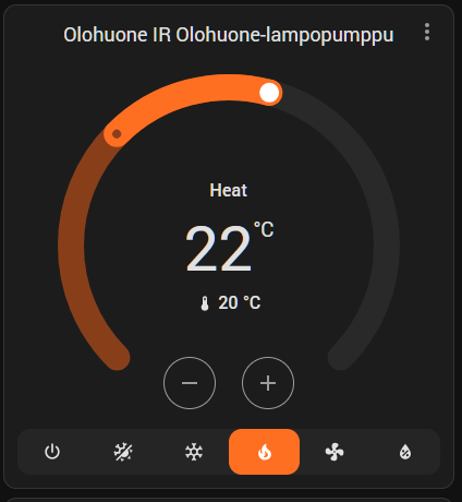
After the electronics are connected and the firmware is programmed, a climate control module will become available in Home Assistant. This module allows you to set temperatures, turn the heat pump on and off, change heating and cooling modes, etc.
The great thing is that all of this can be done remotely, and all available functions can be used in automations as part of an energy-saving routine.
Basic Principle of Operation for ESP32 and ESPHome
Essentially, the system works by programming the microcontrollers with the help of a computer. Home Assistant and the ESPHome integration generate the required firmware package and upload it to the microcontroller. Afterward, the microcontroller connects to Wi-Fi when powered on. Once the initial programming is complete, all subsequent updates are done wirelessly via Wi-Fi, making it very easy to update the configuration. It is managed through Home Assistant, which uploads the changes to the microcontroller.
Steps to Get a Heat Pump Integration Working
Hardware
- ESP32 Board and IR Transmitter: Obtain an ESP32 board and an IR transmitter. Both can be ordered through AliExpress at low prices. For the ESP32 board, it is advisable to have a USB-C socket, and if you do not have soldering equipment or skills, choose a board that already has the pins soldered on. ESP32 Wroom is a common board, so you can search for that.
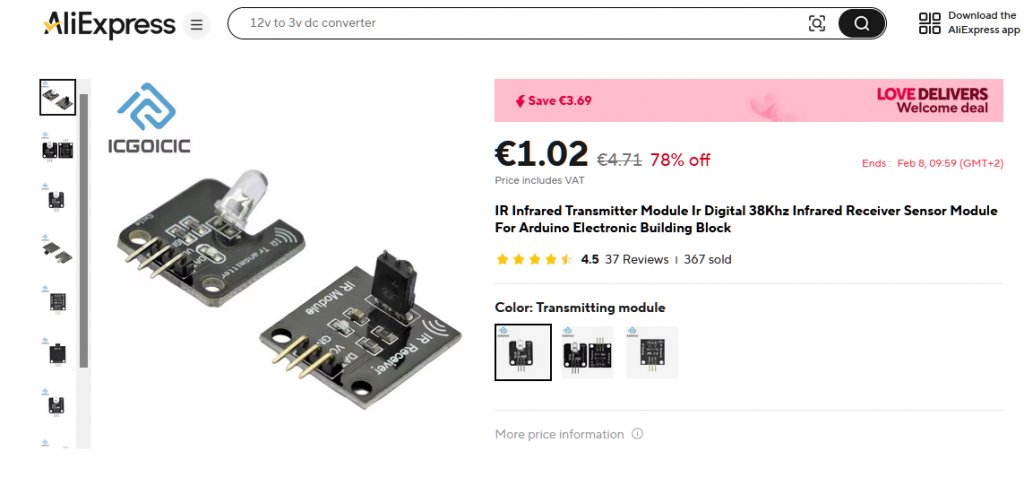
- IR Transmitter and Receiver: It is a good idea to get multiple IR transmitters and receivers since they are very inexpensive. A receiver enables you to debug and capture remote codes and control devices that do not have an integration available or where not all functions are available in the integration.
- Solderless Dupont Jumper Wires: These can be used to connect the pins on the microcontroller to the pins on sensors without soldering. Different options are available from China, and you should get ones with different numbers of pins in the connector. Be sure to get 1-pin connectors since they can be connected in any order. Alternatively, you can solder wires if you have a soldering iron and some wire.
- USB power supply from and old phone: You need to power the microcontroller and an old phone charger is generally good enough for this purpose.
- Computer and USB-C Cable: You need a computer to program the ESP32 microcontrollers and a USB-C cable with data pins connected. A cheap charging cable, such as one that came with your flashlight, will not work.


Software
- Home Assistant with ESPHome Integration: Ensure that Home Assistant is installed and that the ESPHome integration is set up.
Connecting the IR Sensor
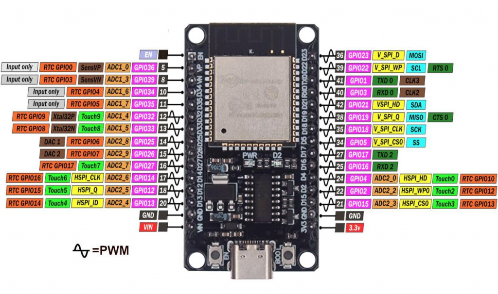
Most active sensors and transmitters require free pins to work, including voltage, ground, and a data pin. For wiring purposes, it is a good idea to select pins that are close together on the ESP32 Dev board. For example, you can use the voltage, ground, and D12 and D14 pins that are adjacent to each other.
It is also important to choose the correct voltage on the ESP board. In one corner, there are pins labeled VIN and GND; these provide 5 volts input voltage from the USB-C connector and ground. On the other side, there is a pin labeled 3V3 and GND; these provide 3.3 volts and ground from the internal voltage regulator on the board.
Most sensors in the Arduino ecosystem operate on 5 volts, but some require 3.3 volts, so be mindful of that.
The product page usually includes instructions and details about these specifications.
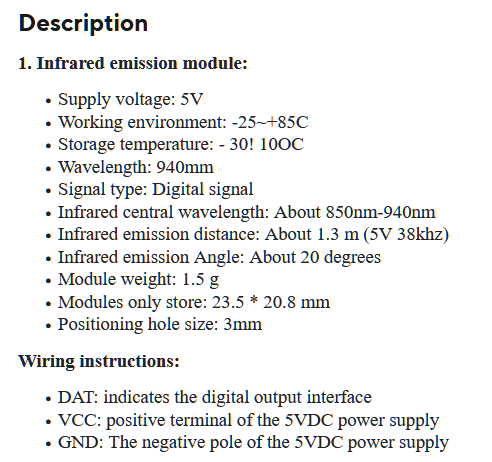
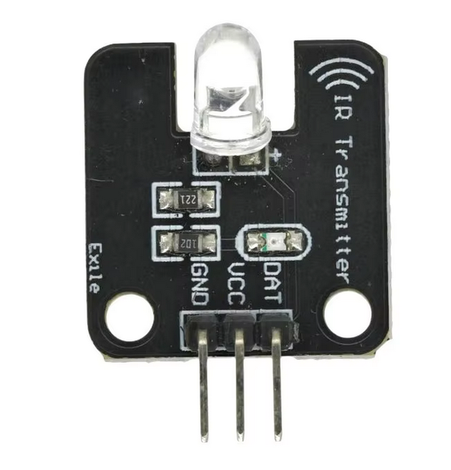
Connecting the IR transmitter is done by wiring the VCC pin from the transmitter to the VIN pin on the ESP32 controller, GND to GND, and DAT to D13.
Programming and Setup
Now that everything is connected, it is time to prepare the ESPHome module. Read through the getting started guide on the ESPHome website.
After you have ESPHome up and running, you can add a microcontroller to your setup using the ESPHome builder in the Home Assistant sidebar. You can either connect the ESP32 device directly to the computer running Home Assistant for programming or download the firmware and upload it through the ESPHome web interface by connecting the ESP32 to your laptop and uploading the firmware binary file created by Home Assistant.
Here is a good guide to help you through the basics: YouTube Tutorial
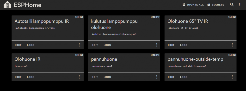
Once you have added your ESP32 to Home Assistant and flashed the firmware onto it, it will connect to Wi-Fi and appear as online in the Home Assistant dashboard.
Now, edit the configuration for the device you added and include the modules needed to control the IR transmitter as well as the heat pump.
esphome:
  name: olohuone-ir
  friendly_name: Olohuone IR

esp32:
  board: esp32dev
  framework:
    type: arduino

# Enable logging
logger:

# Enable Home Assistant API
api:
  encryption:
    key: "SENSURED="

ota:
  - platform: esphome
    password: "SENSURED"

wifi:
  ssid: !secret wifi_ssid
  password: !secret wifi_password

  # Enable fallback hotspot (captive portal) in case wifi connection fails
  ap:
    ssid: "Home Fallback Hotspot"
    password: "SENSURED"

captive_portal:

#If you have an IR receiver, you can uncomment this code block to get
#debug output from it
#remote_receiver:
#  id: rcvr
#  pin:
#    number: GPIO14
#    inverted: true
#    mode:
#      input: true
#      pullup: true
# high 55% tolerance is recommended for some remote control units
#  tolerance: 55%
#  dump: all

remote_transmitter:
  pin: GPIO13
  carrier_duty_percent: 50%
sensor:
  - platform: homeassistant
    name: "Olohuoneen lämpöanturi"
    entity_id: sensor.temperature_3_temperature
    id: olohuone_lampo
climate:
  - platform: heatpumpir
    protocol: toshiba_daiseikai
    horizontal_default: middle
    vertical_default: mdown
    max_temperature: 26
    min_temperature: 17
    name: "Olohuone-lampopumppu"
    sensor: olohuone_lampo
For the remote transmitter, you need to identify the pin it is connected to; for example, D13 is GPIO13.
The sensor component provides a callback to Home Assistant, allowing the integration to display the temperature in the area where the heat pump is operating. This can be skipped if you do not have temperature sensors yet, but it is a nice feature. You will need to provide the device name from Home Assistant here.
The Climate component includes the settings for the heat pump as well as the parameters specific to the chosen model. I am using the HeatpumpIR Arduino library, which offers additional features that the built-in Toshiba module did not have.
remote_transmitter:
  pin: GPIO13
  carrier_duty_percent: 50%
sensor:
  - platform: homeassistant
    name: "Olohuoneen lämpöanturi"
    entity_id: sensor.temperature_3_temperature
    id: olohuone_lampo
climate:
  - platform: heatpumpir
    protocol: toshiba_daiseikai
    horizontal_default: middle
    vertical_default: mdown
    max_temperature: 26
    min_temperature: 17
    name: "Olohuone-lampopumppu"
    sensor: olohuone_lampo
Information on how the Climate component works can be found on the ESPHome Climate Component page. For the IR transmitter-specific component settings, refer to the IR Remote Climate page.
You need to customize the YAML configuration to match your specific heat pump.
Once everything is configured, add the new device to Home Assistant through the settings. It is not enough to configure it through ESPHome; you need to add the device after uploading the configuration.
Now you have a Climate component in your Home Assistant and can start testing and using it.
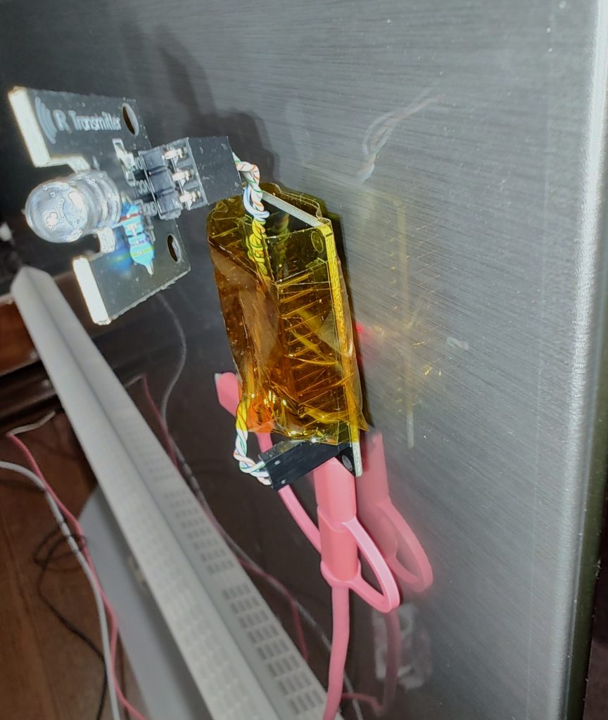
The back of my TV has an ESP32 stuck to it with the transmitter pointed at my heat pump. It is not visible and I have also replaced the resistor for the IR led to improve the range and reliability. It is important to make sure that nothing shorts out so the whole project is wrapped in kapton tape.
Common Problems
- Poor IR Transmitter Range: The IR transmitter has very poor range out of the box. This is because the current-limiting resistor on the IR transmitter is often set very conservatively to save power and prevent issues with devices that have low power. You can replace this resistor with one that allows more power to the IR LED to improve the range.
- Alignment of IR Transmitter: You need to point the IR transmitter precisely at your heat pump for it to work effectively. This is especially important when using a low-power transmitter.
- YAML Syntax Errors: Be careful with the YAML syntax in the ESP configuration. Proper indentation and the correct number of spaces are essential. Incorrect indentation will prevent the configuration from working.